Seismic response modification devices (SRMDs), such as dampers and isolator bearings, have been recently incorporated in many seismic retrofit strategies, particularly in major toll crossing like the ones object of the Caltrans Toll Bridge Retrofit Program. Capacities and sizes of these devices make problematic the characterization of their performance, longevity and wear. For this reason Caltrans supported the development of this dedicated testing facility, capable of real-time 6-DOF dynamic characterizations of full-scale bearing devices and dampers. The facility was completed and became operational in 1999. It was developed jointly by the California Department of Transportation (Caltrans), the Department of Structural Engineering at the University of California, San Diego (UCSD), and MTS Corporation of Eden Prairie, Minnesota. The building (High Bay Physics Laboratory) that accommodates the SRMD Testing Machine is located directly adjacent to the Powell Structural Research Laboratories, with the advantage of direct access to the support services of these labs.


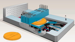
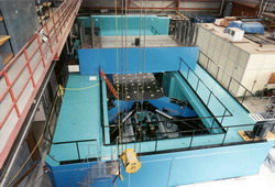
The testing system consists of prestressed concrete reaction frame and a moving platen, connected by four horizontal actuators to the concrete box. The platen, 3.658 m wide by 4.750 m long, slides over four hydraulic hydrostatic low friction bearings attached to the floor of the concrete structure. The platen also extends, for improved stability, with four steel outrigger arms that support four pairs (i.e., upper and lower) low friction slide bearing actuators. The testing system is completed by two additional reaction structures: a removable steel cross beam and a prestressed reaction wall on the west end of the machine, designed for testing dampers. The removable cross-frame and the configuration of the platen make the system flexible to perform in different testing setups, with the characteristics of a unique shaking table. The installation was updated in 2003 with a digital tri-variable controller and a digital off-line simulation for performance prediction and to operate in “shaking table” mode (sponsored by FHWA).
Videos
InquiryDr. Gilberto Mosqueda Danny Innamorato |
| Component | Capacity |
|---|---|
| Vertical Force* | 53,400 kN (12,000 kips) |
| Longitudinal Force* | 8,900 kN (2,000 kips) |
| Lateral Force* | 4,450 kN (1,000 kips) |
| Vertical Displacement | ± 0.127 m ( ± 5 in) |
| Longitudinal Displacement | ± 1.219 m ( ± 48 in) |
| Lateral Displacement | ± 0.610 m ( ± 24 in) |
| Vertical Velocity | ± 254 mm/s ( ± 10 in/s) |
| Longitudinal Velocity | ± 1,800 mm/s ( ± 70 in/s) |
| Lateral Velocity | ± 760mm/s ( ± 30 in/s) |
| Relative Platen Rotation (Roll, Pitch, & Yaw) | ± 2 degrees |
| Maximum Specimen Height | 1.524 m (60 in) |
